
 MICROWIRE is a simple three-wire serial communications interface. This standard protocol handles serial communications between controller and peripheral devices. In this application note are some clarifications of MICROWIRE logical operation and of hardware and software considerations. A typical communication on the Microwire bus is made through the CS, SK, DI and DO signals.
A typical Microwire cycle starts by first selecting the device(bringing the CS signal high). Once the device is selected, a valid Start bit (“1”) should be issued to properly recognize the cycle. Following this, the 2-bit opcode of appropriate instruction should be issued. After the opcode bits, the 8-bit address information should be issued. For certain instructions, some (or all) of these 8 bits are don’t care values (can be “0” or “1”), but they should still be issued. Following the address information, depending on the instruction (WRITE and WRALL), 16-Bit data is issued. Otherwise, depending on the instruction (READ and PRREAD), the device starts to drive the output data on the DO line. Other instructions perform certain control functions and do not deal with data bits. The Microwire cycle ends when the CS signal is brought low. However during certain instructions, falling edge of the CS signal initiates an internal cycle (Programming), and the device
remains busy till the completion of the internal cycle.
1) Read and Sequential Read (READ)
2) Write Enable (WEN)
3) Write (WRITE)
4) Write All (WRALL)
5) Write Disable (WDS)
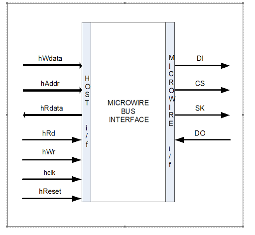
Microwire interface description
| Signal | Name | Description |
| DI | Serial data driven from interface | Input to uwire device |
| CS | Chips select driven from interface | Input to uwire device |
| SK | Serial clock driven from interface | Input to uwire device |
| DO | Serial data driven from uwire device | Input to uwire interface |
Host interface description
| Signal | Description |
| µwire_hif_cs_ni | Active low chip select, this signal is for configuration Registers Access.
|
| µwire_hif_rd_en_i | When asserted the data from the register addressed by the address bus will be kept on the bus read data bus after N clock cycle delay. |
| µwire_hif_wr_en_i | When asserted the data on the write data bus gets written to the register that matches with the address on the address bus in one/two clock cycle. |
| µwire_hif_addr_i [15:0] | Address to access different configuration registers of this core. |
| µwire_hif_wr_data_i [7:0] | Data to be written to the addressed register. |
| µwire_hif_rd_data_o [7:0] | Data read from the configuration register.Data becomes valid after latency of N Clocks. |
| µwire_hif_intr_o | This is interrupt line. This line will be high until all interrupts in register are read. |


Configuration Registers :
1. Control Register
2. TDR_addr Register
3. TDR_data Register
4. Status Register
5. RDR Register
6. Revision Register
Operation command from processor
Read – 000
Write – 001
Write ALL – 010
Erase ALL – 011
Erase – 100
EWEN – 101
EWDS – 110
With this information , anyone can built the microwire ip from scratch for learning purpose.
Bạn Có Đam Mê Với Vi Mạch hay Nhúng - Bạn Muốn Trau Dồi Thêm Kĩ Năng
Mong Muốn Có Thêm Cơ Hội Trong Công Việc
Và Trở Thành Một Người Có Giá Trị Hơn
Bạn Chưa Biết Phương Thức Nào Nhanh Chóng Để Đạt Được Chúng
Hãy Để Chúng Tôi Hỗ Trợ Cho Bạn. SEMICON
