
Deinterlacing is a video processing function that is required to address legacy problems stemming from the generation of interlaced video that was widely used by the old analog CRT televisions.
An interlaced video is a succession of 50/60 fields per second, where each field carries only half of the rows that are displayed in each frame of video.
In some ways interlaced video was an elementary compression technique when older display technologies were based on cathode ray tubes (i.e. CRTs).
Today deinterlacing video is an important video processing function, as much of the video content is available in the legacy interlaced format and almost all of the newer displays -- LCD or Plasma -- require progressive video input. While deinterlacing is required in many systems, it is by nature complex and no deinterlacing algorithm can produce a perfect progressive image.
This article explores the different deinterlacing techniques and examines how FPGAs are increasingly being used for any sufficiently complex deinterlacing function. The article also examines the hardware tradeoffs when implementing different deinterlacing algorithms.
Deinterlacing Background
Figure 1 shows how these two fields contain the pixels in one frame. Also note that each field is recording pixel values that are separated in time.
Basic Deinterlacing Techniques
Fundamentally, deinterlacing is the process of taking a stream of interlaced frames and converting it to a stream of progressive frames. The two basic methods are commonly referred to as 'bob' and 'weave'.
With the 'bob' deinterlacing technique each field can become its own frame of video, so an interlaced NTSC clip at 29.97 frames per second stream becomes a 59.94 frame per second progressive. Since each field has only half the scanlines of a full frame, interpolation must be used to form the missing scanlines.
'Bob' deinterlacing can also be described as spatial line doubling, in which the lines in each field are doubled. The new line generated can either be just a copy of the previous line or computed as an average of the lines above and below, as shown in Figure 2.

'Bob' deinterlacing provides a good result when the image intensity varies smoothly, but it can soften the image since it reduces the vertical resolution.
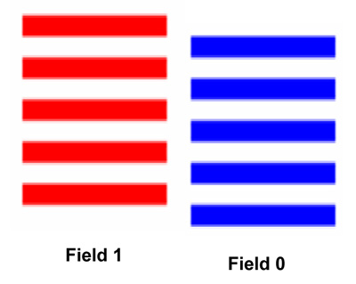
The 'weave' technique for deinterlacing involves 'weaving' two fields, which are separated in time into one full frame as illustrated in Figure 3. Weave provides good results if there is no motion in that 1/60th of second that separates the two fields (for NTSC video). But motion can create artifacts such as the mouse teeth artifacts that are shown in Figure 3.
The results of the weave algorithm can sometimes be perfect when pairs of interlaced fields have been created from original progressive frames.

Figure 4: Differences between 'bob' and 'weave' deinterlacing
Both bob and weave deinterlacing can impact the image quality, especially when there is motion. The bob method softens the image and the weave method can create jagged images or mouse teeth artifacts. Figure 4 contrasts the images generated using both the bob and the weave techniques.
Advanced Deinterlacing Techniques
An obvious way to get better quality deinterlacing would be to mix up both the techniques described in the preceding section, first computing if there is or not motion between successive frames of video.
This technique that would advocate the weave technique for static regions and the bob technique for regions that exhibit motion, is referred to as 'motion adaptive deinterlacing'.
The key to motion adaptive deinterlacing is to obtain accurate motion detection-- this is typically done by comparing an m x n matrix of pixels from one frame to the next. Following is a simple motion adaptive deinterlacing algorithm description:
- First, collect the pixels from the current field and the three pixels preceding it, this creates two frames -- a current and a previous as shown in Figure 5.
- Next, assemble these pixels into two groups of 3 x 3 pixels, one for the current frame and one for the previous frame
- Then, calculate the difference in the pixel values (also called motion values) between the two frames

The motion value calculated can be used as is or compared to the previous motion value generated. If the previous motion value is higher, then the current motion value is adjusted so that it is between the calculated amount and the previous amount. This additional computation is also called the 'motion bleed'.
If this algorithm is selected, the motion values from more than one frame in the past are carried over. It is an exponential decay; after a motion, it may take 3 to 10 frames before the 'weave' is again stabilized.
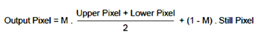
In either case, based on the motion value, either the weave algorithm is selected or the new pixel is calculated by spatial interpolation of the upper and lower pixels.
A simple equation that computes a weighted mean of the new pixel generated by interpolation or the weave algorithm (output pixel in the previous field) is shown here:
Cadence Detection
Interlaced video can be even more complex than just the transmission of odd and even fields. Motion picture photography is progressive and is based on 24 frames per second, whereas the NTSC format is 60 fields per second. This means that the conversion of motion picture photography into interlaced video creates even more complex cadences.
To convert motion picture photography to interlaced video each progressive frame is converted into two fields, which increases the frame rate to 48 fields per second. To increase this to 60 fields per second, a 3:2 pull-down technique is used that generates 3 fields from one film frame and 2 fields from the other film frame. This is known as '3:2 cadence'.
Figure 6 shows the conversion of a 24fps to interlaced video using a 3:2 pull-down technique. Although 24fps film and its associated 3:2 video cadence is the most common format, it is not the only cadence used today.

Sometimes every twelfth field is dropped -- to accelerate the film and fit it within a given time slot. This can be barely noticed by an average viewer, but it results in a 3:2:3:2:2 cadence. This means the following conversion:
Frame 1 >> 3 Fields
Frame 2 >> 2 Fields
Frame 3 >> 3 Fields
Frame 4 >> 2 Fields
Frame 5 >> 2 Fields
Repeat
The variety of cadences does not end there. Professional camcorders use different types of cadences. Even other cadences are created by different kinds of video processing.
Cadences represent a challenge for deinterlacers since there must be a comparison made between the incoming fields to detect the cadence. Most deinterlacers can detect commonly used cadences such as 3:2 and implement the right deinterlacing technique. But more esoteric cadences might not be detected, which results in throwing away the video data.
It is also conceivable that one part of the frame might have 3:2 cadence; while the other part may be straight interlaced (i.e. a film is inserted in an interlaced video). To detect and correctly deinterlace such a source would require deinterlacers to implement a per pixel cadence detection. All this would add to the complexity both in terms of logic and external memory accesses.
Motion Compensated Deinterlacing
Motion compensated deinterlacing is by far the most advanced deinterlacing technique and it uses the motion compensation techniques generally used for video compression. While this technique is not described in detail here, it basically looks at more than one field to determine motion for a block of pixels. It estimates the motion for this block and shifts the pixels to compensate for the motion. This type of deinterlacing would be the most computationally demanding technique, but would have the best output quality.
Hardware Considerations
Deinterlacers are ideally implemented in hardware - generally FPGAs are used to implement sophisticated high definition (HD) deinterlacers.
The key hardware resource required to build a highly efficient deinterlacer is memory. This applies to both on-chip memory to store the m x n block of pixels across the different fields (the calculated and previous motion value matrices) as well as the external (generally DDR) memory to store multiple input video fields and the calculated frames.
Table 1 shows the resources used to implement a motion-adaptive deinterlacing algorithm on a PAL video source in an Altera FPGA.
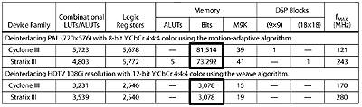
The table contrasts the resources used for a motion adaptive technique with the resources used for a simple 'weave' technique. Notice the drop-off in the amount of memory used even though the weave technique is applied to a higher resolution image.
Additionally a deinterlacer requires frequent external memory access, thus an important consideration in the design of a deinterlacer is the expected memory bandwidth.
To buffer one field of a 480i video source requires 165.7MBit/s:
(720 * 240 pixels/field) * (16 bits/pixel) * (59.94 fields/sec)
The bandwidth doubles for a progressive frame and increases even more for HD video. To calculate the bandwidth, calculate the number of frame accesses that a deinterlacer has to do and then add the total bandwidth. Compare this to the expected bandwidth of the DDR memory interface, which will depend on the throughput and the width of the memory interface.
Conclusion
For many infrastructure, military, and industrial systems FPGAs are the ideal platform for implementing high quality video deinterlacing. While the complexity of the deinterlacing algorithm implemented is driven by system needs, sophisticated deinterlacing solutions are available from FPGA vendors to assist in starting designs.
FPGA vendors have invested in various video IP and reference designs that showcase different methods of deinterlacing HD video. These solutions can be used as a starting point for system design.
About the author
Suhel Dhanani is a Senior Manager in the software, embedded and DSP marketing group, and is responsible for DSP product marketing. He has over 15 years of industry experience in semiconductors -- with both large companies such as Xilinx and VLSI Technology as well as with Silicon Valley startups including Anadigm and Tabula. Mr. Dhanani has completed a graduate certificate in Management Science from Stanford University and holds M.S.E.E. and M.B.A. degrees from Arizona State University. He can be reached via
This e-mail address is being protected from spambots. You need JavaScript enabled to view it
.
(Theo digitalhomedesignline.com)