| | Subtracter |
| | Subtracter circuits take two binary numbers as input and subtract one binary number input from the other binary number input. Similar to adders, it gives out two outputs, difference and borrow (carry-in the case of Adder). There are two types of subtracters. |
| | - Half Subtracter.
- Full Subtracter.
|
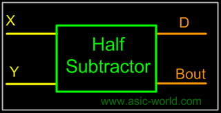
| | Half Subtracter |
| | The half-subtracter is a combinational circuit which is used to perform subtraction of two bits. It has two inputs, X (minuend) and Y (subtrahend) and two outputs D (difference) and B (borrow). The logic symbol and truth table are shown below. |
| | Symbol |
| |  |
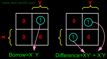
| | Truth Table |
| | | X | Y | D | B | | 0 | 0 | 0 | 0 | | 0 | 1 | 1 | 1 | | 1 | 0 | 1 | 0 | | 1 | 1 | 0 | 0 | |
| | From the above table we can draw the Kmap as shown below for "difference" and "borrow". The boolean expression for the difference and Borrow can be written. |
| | 
|
| |  |
| | From the equation we can draw the half-subtracter as shown in the figure below. |
| | 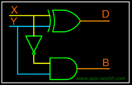 |
| |
|
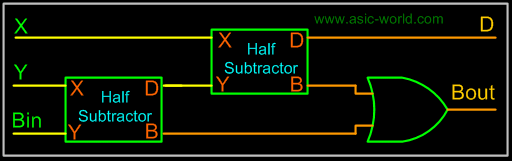
| | Full Subtracter |
| | A full subtracter is a combinational circuit that performs subtraction involving three bits, namely minuend, subtrahend, and borrow-in. The logic symbol and truth table are shown below. |
| |
|
| | Symbol |
| | 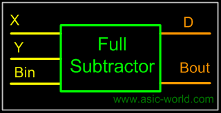 |
| |
|
| | Truth Table |
| | | X | Y | Bin | D | Bout | | 0 | 0 | 0 | 0 | 0 | | 0 | 0 | 1 | 1 | 1 | | 0 | 1 | 0 | 1 | 1 | | 0 | 1 | 1 | 0 | 1 | | 1 | 0 | 0 | 1 | 0 | | 1 | 0 | 1 | 0 | 0 | | 1 | 1 | 0 | 0 | 0 | | 1 | 1 | 1 | 1 | 1 | |
| |
|
| |  |
| |
|
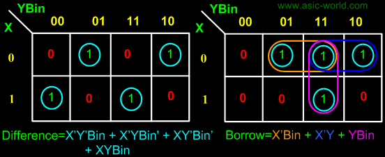
| | From above table we can draw the Kmap as shown below for "difference" and "borrow". The boolean expression for difference and borrow can be written. |
| |
|
| | D = X'Y'Bin + X'YBin' + XY'Bin' + XYBin |
| | = (X'Y' + XY)Bin + (X'Y + XY')Bin' |
| | = (X Y)'Bin + (X Y)Bin' Y)'Bin + (X Y)Bin' |
| | = X Y Bin |
| | Bout = X'.Y + X'.Bin + Y.Bin |
| |
|
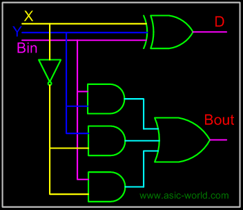
| | From the equation we can draw the half-subtracter as shown in figure below. |
| |
|
| |  |
| |
|
| | From the above expression, we can draw the circuit below. If you look carefully, you will see that a full-subtracter circuit is more or less same as a full-adder with slight modification. |
| |
|
| |  |
| |
|
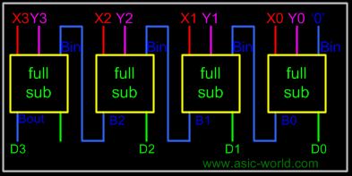
| | Parallel Binary Subtracter |
| | Parallel binary subtracter can be implemented by cascading several full-subtracters. Implementation and associated problems are those of a parallel binary adder, seen before in parallel binary adder section. |
| | Below is the block level representation of a 4-bit parallel binary subtracter, which subtracts 4-bit Y3Y2Y1Y0 from 4-bit X3X2X1X0. It has 4-bit difference output D3D2D1D0 with borrow output Bout. |
| |
|
| |  |
| |
|
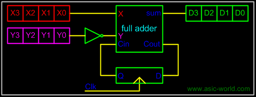
| | Serial Binary Subtracter |
| | A serial subtracter can be obtained by converting the serial adder using the 2's complement system. The subtrahend is stored in the Y register and must be 2's complemented before it is added to the minuend stored in the X register. |
| |
|
| | The circuit for a 4-bit serial subtracter using full-adder is shown in the figure below. |
| |
|
| |  |
| |
|
| | Comparators |
| | Comparators can compare either a variable number X (xn xn-1 ... x3 x2 x1) with a predefined constant C (cn cn-1 ... c3 c2 c1) or two variable numbers X and Y. In the first case the implementation reduces to a series of cascaded AND and OR logic gates. If the comparator answers the question 'X>C?' then its hardware implementation is designed according to the following rules: |
| |
|
| | - The number X has two types of binary figures: bits corresponding to '1' in the predefined constant and bits corresponding to '0' in the predefined constant.
- The bits of the number X corresponding to '1' are supplied to AND gates
- The bits corresponding to '0' are supplied to OR logic gates
- If the least significant bits of the predefined constant are '10' then bit X0 is supplied to the same AND gate as bit X1.
|
| |
|
| | If the least significant bits of the constant are all '1' then the corresponding bits of the number X are not included in the hardware implementation. All other relations between X and C can be transformed in equivalent ones that use the operator '>' and the NOT logic operator as shown in the table below. |
| |
|
| | | Initial relationship to be tested | Equivalent relationship to be implemented | | X<C | NOT (X>C-1) | | X<= C | NOT (X>C) | | X >= C | X>C-1 | |
| |
|
| | The comparison process of two positive numbers X and Y is performed in a bit-by-bit manner starting with the most significant bit: |
| |
|
| | - If the most significant bits are Xn='1' and Yn='0' then number X is larger than Y.
- If Xn='0' and Yn='1' then number X is smaller than Y.
- If Xn=Yn then no decision can be taken about X and Y based only on these two bits.
|
| |
|
| | If the most significant bits are equal then the result of the comparison is determined by the less significant bits Xn-1 and Yn-1. If these bits are equal as well, the process continues with the next pair of bits. If all bits are equal then the two numbers are equal. |