


De-multiplexers
They are digital switches which connect data from one input source to one of n outputs.
Usually implemented by using n-to-2n binary decoders where the decoder enable line is used for data input of the de-multiplexer.
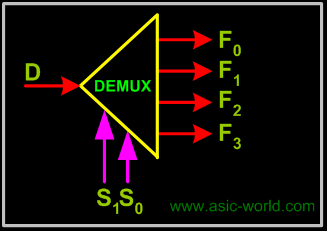
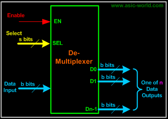
The figure below shows a de-multiplexer block diagram which has got s-bits-wide select input, one b-bits-wide data input and n b-bits-wide outputs.
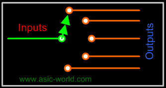
Mechanical Equivalent of a De-Multiplexer
The operation of a de-multiplexer can be better explained using a mechanical switch as shown in the figure below. This rotary switch can touch any of the outputs, which is connected to the input. As you can see at any given point of time only one output gets connected to input.
1-bit 4-output de-multiplexer using a 2x4 binary decoder.
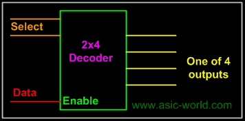
Example: 1-to-4 De-multiplexer
Symbol
| Truth Table | ||||||
| . | ||||||
| S1 | S0 | F0 | F1 | F2 | F3 | Â |
| 0 | 0 | D | 0 | 0 | 0 | Â |
| 0 | 1 | 0 | D | 0 | 0 | Â |
| 1 | 0 | 0 | 0 | D | 0 | Â |
| 1 | 1 | 0 | 0 | 0 | D | Â |
Bạn Có Đam Mê Với Vi Mạch hay Nhúng - Bạn Muốn Trau Dồi Thêm Kĩ Năng
Mong Muốn Có Thêm Cơ Hội Trong Công Việc
Và Trở Thành Một Người Có Giá Trị Hơn
Mong Muốn Có Thêm Cơ Hội Trong Công Việc
Và Trở Thành Một Người Có Giá Trị Hơn
Bạn Chưa Biết Phương Thức Nào Nhanh Chóng Để Đạt Được Chúng
Hãy Để Chúng Tôi Hỗ Trợ Cho Bạn. SEMICON