


I2C Bus Description
I2C bus was developed by Philips Semiconductors [NXP], originally designed to be a battery control interface.
The I2C interface standard defines both the electrical layer and protocol layer.
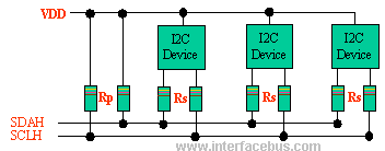
The I2C bus uses a bi-directional Serial Clock Line [SCL] and Serial Data Lines [SDA]. Both the SCL and SDA lines are pulled high via an Rp resistor.
Resistor Rs is optional, and used for ESD protection for 'Hot-Swap' devices. No other lines are specified. Any device may be a Transmitter or Receiver, and a Master or Slave. Data and clock are sent from the Master ~ valid while the clock line is high. The link may have multiple Masters and Slaves on the bus, but only one Master may be active at any one time. I2C Slaves may receive or transmit data to the master.
I2C Interface Circuit Schematic Diagram
I2C Bus Speed
There are a number of speed grades available depending on the I2C interface specification version
Three speed modes are specified in the 2001 I2C standard version:
Standard; 100kbps [Bits per Second], Fast mode; 400kbps, and High speed mode 3.4Mbps [HS Mode].
While the 2006 I2C version defines the Fast Mode Plus speed grade which increase the bus speed to 1MBps [1MHz].
I2C Communication
I2C, due to its two-wire nature (one clock, one data) can only communicate half-duplex. The maximum bus capacitance is 400pF, which sets the maximum number of devices on the I2C bus and the maximum line length. The interface uses 8 bit long bytes, MSB [Most Significant Bit] first, with each device having a unique address.
Remember that the I2C bus is defined as having a maximum capacitance of 400pF, that defines the maximum number of I2C components on the I2C bus and the I2C length [in combination]. So the I2C Bus length is never defined in the I2C Bus specification. However, there is one note in the interface specification: If the length of the bus lines on a PCB or ribbon cable exceeds 10 cm and includes the VDD and VSS lines, the wiring pattern must be: SDA - [Power/Ground or Ground] - SCL, or no Vdd/Vss lines if there embedded within the PCB.
Of course this could also be a twisted pair or shielded cable but I2C cable length still depends on the type of cable [and its capacitance] and the number of I2C devices.
Each I2C device is defined to have 10pF per I/O pin [maximum].
I2C Bus Voltage Levels
The voltage VDD may be different for each device, but all devices have to relate their output levels to the voltage produced by the pull-up resistors [RP] It is possible to run off two different bus voltages, but they have to be translated [refer to the spec.]. The I2C serial interface above show the I2C Pull-Up connecting to Vdd [supply voltage].
I2C Bus Terms
The I2C bus may also be seen as the Inter-IC Bus or the IIC Bus which all mean the same thing. The most common term is of course I2C. Of course there are always other references; I2C Serial Port, I2C Digital Interface, I2C Interface or I2C Interface Specification.